Monday, November 29, 2010

Slip Ring Soldering and Installation

I did a small parts buy of 50 of these slip rings a couple of months ago and sold them to club members. I'm not electronics expert and my soldering has be limited to things like speaker wire and car stereos. I never did boards like this and don't quite have the tools to do this right. However my friend Rich does! He's an electronics expert who rebuilds Porsche CPUs on the side. So he taught me some lessons.

Rich uses a CSI-STATION1A from Circuit Specialists Inc. Pretty good deal for $30 bucks. 
He decided to start off with the easy piece first the Slip Ring Connection Kit. 


This is a pretty straight forward deal and pretty simple. First read the manual get to know the job. Then add all the components you see here. Rich advised not to use a pointed tip and to use a flathead tip.Using 22 gauge solder you touch the solder tip to one side of the component and let it heat up for a few seconds. Then apply the solder on the side and let it melt and wrap around the little stub. Then solder each one methodically. After Rich finished one of these boards I did the other one. I took about 20 minutes or so per board. I have to admit it was a good lesson to get your feet wet if you never did this before.

Rich then checked out each solder for holes using a 25x jewelers glass. My HD camera's macro shot here does the same but shows dozens at a time. Where as his shows a single one of these contacts in full screen view.

Now is the harder portion of doing this.

With one hand you hold the wire it don't matter which one to the first DB 25 connector. With your other hand you move the soldering gun tip to the either side of the port. With your 3rd hand you add the solder after you allow a few seconds for the connector to heat up. You might need two people for this or a set of helping hands and a large magnifying glass is a must. 

We did a continuity check on each wire to make sure each one was the same on both db 25 connectors. Note there are two blue wires. Make sure you're sending the right signals through the proper wires. Then its plug and play after this. Also note on this Scott has determined that port 7 is not used. There are 24 wires in the slip ring and 25 possible contacts on these connectors. Thus 1 channel is not used.
 When your done it should look something like this. Now to install this in your droid you simply just very carefully put the bottom port of the slip ring there your frames center hole.

I decided that I wanted to mount the female board on my electronic drop down panel. But the slip ring wires aren't long for that so I need to order 1-2 feet DB 25 extension cable.

So I redid my electronic panel already. I mounted some of my boards side ways to try to utilize the space more. I had to move the JEDI control because last time it touched the Pitman motor as you can see the holes left over.

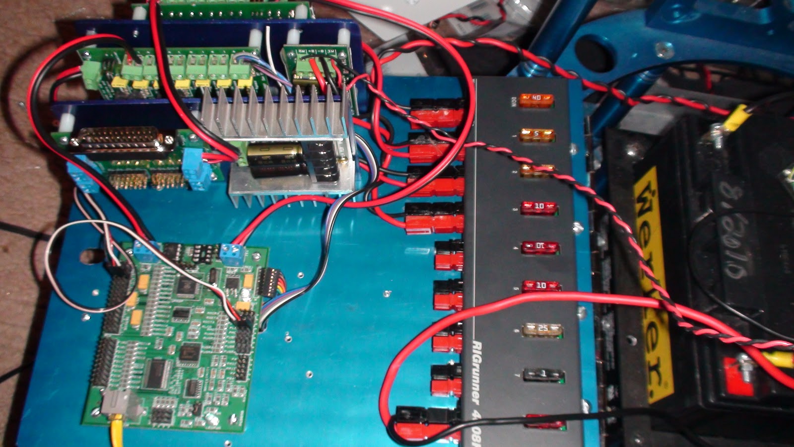
You end up using these 12 volt connections fast and I don't even have the feet motor controller wired yet. I need to go back and make sure what I do have hooked up is fused properly.

At last, I have now power to the top via the slip ring and confirmed on one channel I powered up in the body. Now I need to mount this board in the head.

Here is a look inside R5-D4's head! The slip ring connection kit receives 12 volt power from the body. It powers up that purple LED RC board that I control with a remote. There is plenty of room in this head left. In 2011 I plan to upgrade this R5 head and open all the panels with hinges and servos now I have the electronics in place to get started.

The back panel is now hooked up like this. LCD to read the JEDI feedback, voltmeter, memory card and Vex receiver with the vmusic2. This will change as I add more parts and reconfigure as I go.


Now my droid looks like this. 


Thursday, November 11, 2010

J.E.D.I. Control Installed

After a couple of days of wiring this up and testing it. I have installed most of Scotts J.E.D.I. Control system into my droid. Now my droid is getting out of the static category to actually doing something.

Pictured here is my electronics panel with a Rigrunner 4008H 
to the upper left is the 12v input from the on/off switch. Next to that 2 wires run down to Dan's Power distribution version 2.1 and 2.2 boards to convert 12v to 5v and feed into the J.E.D.I.Controller. In the center is the Syrene2x25 motor controller that a servo port feed controls the Pittman motor spinning the dome. The final power port is running to the 12v amp.

The two power distribution boards are temporary to get this up and running. When I get the DC/DC converters these probably won't be needed and I'll save twice as much space.
With the panel up I still have plenty of room, but limited space to put some more electronics. Now that most of the JEDI is mounted I kinda of look back on what I should have done. A few things I know I want on the back panel. 

1. Easy access to the SD memory card that runs the droid is a must have item. I plan to take this card out a lot and adjust the startup files, or writng my own routines and test them out.

2. The LCD that shows feedback on what the JEDI is reading from the droid wrangler. It would be cool to have the items with the most LED lights on the backside so it looks cooler when the door is off or open.

Oh snap!
I can't close my electronic panel! The Vex area on the J.E.D.I. controller is hitting the Pitman motor:( I only need about 3mm more and it would lock. I have no room left to move it so one of the power distribution boards will have to move and I'll change the wiring to make space. Damn, I  cut a hole in the back door to run the vmusic cables for nothing!

So I'm going to have to take this all apart, rewire it and move the JEDI board for sure atleast 1/2 inch inward. I find it sucks tapping 4-40 holes in aluminum so I need to order 4 more taps for all this AL work I foresee. I break them every 40 holes. There's already 1 broke 4-40 tap in this blue panel:) All the other sizes I've never broke one but these are so small eventually it snaps in the hole after some usage.

Well atleast now I have dome control I can rotate this noise thing left or right.!
Now with dome rotation it was and understatement to say it was cool to see it turn left and right from RC control. That was a new milestone passed since this project started nine months ago. I now have power over the sound, dome and servos and soon movement in a couple of months.

However none of this works perfectly and there's always some bugs to work out.

1. The I have to turn up the amp on full settings to here the vmusic sounds properly. The result is a loud buzz. This was be expected. I probably have to get another amp. This one is too big anyway. I'll check astromech and try out a different amp to resolve this.

2. The dome spins okay clockwise at sufficient speed. Spinning it counter clockwise its very loud and only 1/4 of the speed . This suggests some resistance. This was an issue before any of this electronics so I'll check out how level the dome is. It works okay without the R5 head on top of it.

3. I'm ordering some thinner wire and rewiring this all next week. I'll double up the power boards so they are ontop of each other. The JEDI Control board has to be on the inside panel. Because all the servo connections can't be reached if its on the other side. The power boards must also be on the same side as the Rigrunner and JEDI board. The motor controls can go on either side. I'm also thinking about putting this in the droid soon to give me control over 16 more servo/motor options.

Basically I'll wire this up probably for 12volt  from the Rigrunner. Then put it somewhere in the droid. Then I can trigger 'something' to happen. 
Four micro servos plugged in to test the system. So far so good! I need to figure out how to hook up servos from channel 7-16 and control them with the VEX remote. I hope my next update is how I figured out how to make these servos open and close some doors.
 

Thursday, November 4, 2010

Gluing the front inner and outer AL Skins

Okay, finally another update. I've been out of town and worked on a few things. I decided to focus on completing the front skins. I don't have all the parts I need like center vents or coin slots so I'm going for it anyway. I used the 3M(TM) VHB(TM) Adhesive Transfer Tape F9460PC Clear, 1/2 in x 60 yd 2.0 mil , 2 sided tape first.
Here is the tape all applied before I took off the back side. I let it sit for a day because I just copy what Paul does on his blog. :) It seems to bond better if you wait a while and press down a on the tape on your first surface its placed on. 

To make sure the inner and outer skins align. Make sure your coin slot is installed. That serves as an alignment key. After the tape comes up it seems to nearly wrap itself in place.

Now I have joined the two together using 144 mini clamps I bought from Office Max for $6 bucks. Its cheaper then buying a bunch of mini claps from Home Depot and does the same job. I don't know what the clamp record is for doing this job but I was certainly going for it. There's probably room for 200 clamps on the next one! Also note I glued the skins together with the doors on. I don't know why or if that is necessary but that's how I did mine.

My biggest mistake doing this entire process was using those tiny red clamps you only see one in this photo on the top right. However I later added 5-6 more of them later one and with no plate or masking to protect my painted skin. They are so strong they damaged the paint in every spot I used them. Now I have to mask and repaint and start over due to all the damage they did. The other clamps were okay but I guess I learned as I go.

Now the two skins are bonded. I started to superglue and use Goop to bond the five outer door skin panels. Here I'm doing the charging bay door. On some of my skins I used way too much JB weld but that sands down really fast with a dremel. My favorite clamps are the blue ones with yellow tips. You can squeeze them really, really tight. My second favorite is the black plastic orange tips. They clamp really tight but don't do damage to my parts. The other black handed red tip ones are pretty weak and it seems I have tons of them. Clamp wise, get half a dozen of the blue/yellow tipped clamps and some of the orange tipped ones.

Here is the front view. The superglue only takes about 20 minutes to dry and then you can move on to the next panel.

I have painted all the panels with the inner and out layers glued together. I sanded them and added more glue where needed. I got rid of excess JB weld. I also made a bunch more Coin Returns. There seems to be enough left over aluminum from these skins to make three to four complete sets out of. I made so many Coin Returns I pretty much have the cuts memorized now.


Now I have the utility doors area glued in and filed down. I had paint damage from the clamps and sanded that down. Notice the brown JB weld around the utility doors.

Builders, notice the grey color thats on the inner and outer skins. I used very, very thin coats of JB weld, and sanded and repeated this two more times until I had it to how I wanted. So its just about time to mask and paint and put the doors on. I want to install the J.E.D.I . Control next week and have this project donish.

 Now I have it taped up and ready for another coat of paint. It took maybe 20 minutes to put on the blue tape and finish it. 

And now the wait is over. The skins are finished being taped together, then spot super glued all over and then JB welding certain spots of both skins together and finally repainted.

The paint job is done, on Sunday it will be done drying in the sun. Then I can glue in the coin return and side pocket vent. Mount this to the frame and start planning on how I"m going to put servos on these doors. I also need to get the center vents and power coupler on the skins to finish it. Oh yeah, I need to get that coin slot done too. So many projects so little time.

For all the new people who just got in on the current run of the John Sherrell aluminum skins I hope this little blog helped map out your build. I also suggest checking out Pauls blog and Victor Francos blog on how they tackles the aluminum skins.Now the fun begins in this journey with the servos next.