Sunday, June 26, 2016

More work on 3P0
I have a bunch of aluminum arrive recently so work progresses on this project.
I realized the neck area will take alot of stress so I made some plates to reenforce this area so the entire head isn't stressing the fiberglass.
 The plate installed from the top.
 View of plate from the bottom.
 The plate is hard to see with the head on. It will be hidden by the neck after I figure out how I'm doing the neck. One problem is the head won't turn left or right now. These plates pushed the servo down so far the linkage don't connect. So after a trip to Ace Hardware I got smaller spacers on the servo and now it work again. So I can continue to play around with the head with my transmitter and have friends toy with it and not worry about the fiberglass cracking in that area. If it does crack I won't see it under the round plates until the head one day snaps off.
 The belly section is simply some ribbed rubber with any spare or junk wires you have laying around. I'm not sure how to attach them just yet and have little clips holding them in place. I might JB weld the wire ends onto the top part of the rubber. Then JB weld magnets on the rubber to attache to magnets on the inside of the torso.
 With the torso over the belly it starting to look more official now. In my next update I'll get to working on the skeleton and how this will rotate and bend over a little.
 This the battery box I made today that will power this droid. A single 12 volt that will be strapped into this box. On top of this will be a 6 inch rockler bearing that will be arriving in a couple of days. Then a top plate over the ring and the skeleton will mount onto that. This is 12x6 inches. It won't fit inside the torso but it's not supposed to. This will eventually sit around where the shorts will be. I don't have shorts so I have no idea what size to make this. I can cut this down to smaller when the time comes if I need to.
 These are the legs I have. One of them is cracked and will need to be repaired the other leg is just fine. These will need a hell of a lot of clean up work to remove the areas where the mold seams are. So I picked the leg with out the crack to start on and see how much work this will need to get this part looking good.
 Here is one side after alot of dremel work. Its so hot outside now around 110 I'm worried I'll over heat my dremel so I use it on and off. Next time I'll have both of mine and after I use 1 for 5 minutes I'll put in a bucket with freezing cool packs so it can cool down and rotate them doing this. These are made out of resin this creates a hell of a mess. Then center ring area of these legs will need a small fine bit to get the material removed. I'm always up for a challenge.
 This is turning out decent. It will need some bondo work in places. This all depends on how much detail I want. Most of us make these so accurate down to the 1 foot distance of stuff nobody will ever see.
Unless you butcher this only fellow 3P0 builders who have the eye on how every inch needs to look, nobody will ever know if you have small mess ups. The average person looks at something like this for a minute as they wait for a selfie. Then get a photo standing a few seconds away from it and walk away. This droid won't have the $2,000 paint job but to make up for that most of it will be animated to the point I can let some kids play with this robot.
I have more parts incoming but my next update will be on my R4 and R5 fiberglass domes that I'm about to get my hands on.
I realized the neck area will take alot of stress so I made some plates to reenforce this area so the entire head isn't stressing the fiberglass.


Unless you butcher this only fellow 3P0 builders who have the eye on how every inch needs to look, nobody will ever know if you have small mess ups. The average person looks at something like this for a minute as they wait for a selfie. Then get a photo standing a few seconds away from it and walk away. This droid won't have the $2,000 paint job but to make up for that most of it will be animated to the point I can let some kids play with this robot.
I have more parts incoming but my next update will be on my R4 and R5 fiberglass domes that I'm about to get my hands on.
Saturday, June 18, 2016
My Animatronic C-3P0 Project
Now that I have 2 astromechs done with basic construction. I'm moving forward on a plan I had over 6 years ago to create a full sized animatronic C-3P0.
 I started with a SPT200 Direct Drive Pan & Tilt System I bought from Servo City and I put the kit together. It's rated to move around 2 pounds which is exactly what my fiberglass C-3P0 head weighs.
 I got parts of an awesome 3P0 from Randy over at SithPlanet.
 I marked on the neck area where I need to drill out the holes needed to mount the lower servo. I'm not using the black plastic lower mounting plate at this point because that is going to be replaced by the neck section.
 So it turned out this was pretty easy to do. Now I have the pan and tilt head installed and mounted to the body. For now I'm not using the droids neck area yet so I can adjust and see if I can get this all to function.
 After checking out some height issues of how high or low I can place the head onto this pan head and still keep it movie accurate. I drilled out 2 areas on the side of the pan head and added stand offs for 10-32. This will be used to connect the pan head to the 3P0 head.
 The 3P0 had its earring fastened to the head with 10-32 bolts that fastened to a nut to the neck section. So I just bolted them into my stand offs I got from Acehardware. I was wondering if I tighten this too much the earrings would strip out but they held up to alot of pressure. This got me pretty tight but I later added a flat bar (not pictured) over the pan head and by adding that it make this rock solid.
Here is my first test video of it. It seems to work. The servos will need to be slowed down and the EPA needs to be adjusted so they don't hit any part of the body they shouldn't. I'm not sure just yet how to get the servos to stop growling. But this wasn't too bad for a couple of hours of work.
To be continued...


To be continued...
Saturday, May 28, 2016
R2-Q5 is Done!
I finished basic construction on R2-Q5 and later found some photos of this droid from deleted scenes of Return of the Jedi.
I based the paint scheme on this droid based mainly on the Hasbro toy and the few photos of the full sized droid which was on the Deathstar in ROTJ.

 Photos of the droid in front and back. Not the best photos, slightly out of focus.
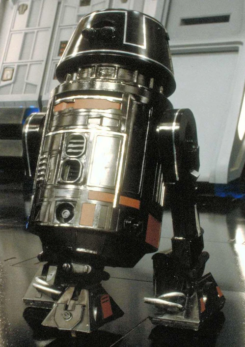
 After looking at these photos of Roger Nichol's droid room showing a full sized R2-Q5 I decided to go with the paint on the real droid and not the toy. This means I have to change a few things, or really paint more stuff and remove paint from the front logics.
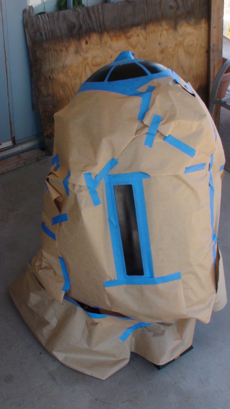
 If you look closely at this deleted scene from the Bluray of ROTJ. R2-Q5 has his large upper panel painted copper along with some of the dome panels. This is not on the Hasbro toy. But I can make my droid more screen accurate knowing this. So its time to get to work. I have this droid going to a Phoenix Comic Con in 7 days and I can't take him apart. So I'll drive him outside and mask and paint him there.

 Now all masked up. I'm going to be painting the large door on 'his' right and all of the panels except the HP.
 In the rear I'm painting the large long panel to match what's in the deleted scene from ROTJ.
So I start painting and notice the can is beginning to run low, the paint is starting to spit out large blobs. Time to go to the store and get another can of the same paint.
Oh, but wait! I'm using Krylon 2908 Copper and they don't sell it no more:( I bought this can 5 years ago and it lasted for all the parts so far. So I run to Home Depot and Lowes they don't sell Krylon at all.
So I go to AceHardware where I bought this can and get Ace brand copper paint which out of the 3 stores is the closest match I found. Amazon has only 6 cans of this paint Krylon 2908 left. But they don't sell via prime and it will take about 10 days to get that paint and I have a Comicon in 7 days.
So what do I do with the 3 panels partly painted? I gotta just use this new paint. With my luck, they are close but don't match:( The new can of paint has a brighter copper and my older paint had a slightly darker copper. But nobody will be able to tell unless I point that out.
 A couple hours after the paint was put on. It's looking much closer to the movie droid from ROTJ now. I still have to paint the outer feet strips copper and remove the front logics and remove the black paint and return that to silver. But I'll do that after the con is over.
 Side view. This is the first photo of it complete with all the parts on it. The newest parts I added are the shoulder hubs and the booster covers. I had resin boosters I was using on this droid. They are smaller than the aluminum versions and they were a bit warped. With these you have to drill and tap where you want the bolts which fasten it to the leg. I could not get the bolts perfectly and just grabbed my blue booster covers off R5-D4 and painted them black. I was running out of time and had to make due.
1 other thing that is not screen accurate are the silver hydro piston thingys are supposed to be black instead of silver. I just think it looks cooler with silver than black, because otherwise hell the entire droid is just black.
 Rear view: Now the back matches what is in the deleted scene that best I could from the above ROTJ photo.
 Me and this guy have a lot of adventures and good times coming soon. I'm pretty happy with how he turned out. When I had the dream of building this droid I just wanted something simple. A black droid that drove, had lights and sounds and that's it. Nothing else, so I kept the skins closed and had nothing else I wanted to do with it.

I can't stop now. I've learned so much over the past 5 years I want to apply all the cool things I did with my R5 and do all of that in this droid where I can.
So I plan to install servos to control atleast the front holoprojector and install some LED light in the front and back and a red light on the top HP.
I'm going to open all the front skin doors and I'm going to use my droid Zapper to come out the little front door on the left like you see when R2-D2 zaps the chain off Leia to free her. I'm going to replicate that since this is a ROTJ droid.
I'm also going to get the utility arms to open and close with servos like I'm currently working on for R5. I have plenty of servos and time to take this to the max.
 I'm also getting another dome so I can convert this droid to R5-J2. I just need the dome and I have plenty of parts to swap and make this droid which look like it can kill people on the Deathstar who don't belong there.
Let's hope they have plenty of imperial droids in Rogue One!
I based the paint scheme on this droid based mainly on the Hasbro toy and the few photos of the full sized droid which was on the Deathstar in ROTJ.



So I start painting and notice the can is beginning to run low, the paint is starting to spit out large blobs. Time to go to the store and get another can of the same paint.
Oh, but wait! I'm using Krylon 2908 Copper and they don't sell it no more:( I bought this can 5 years ago and it lasted for all the parts so far. So I run to Home Depot and Lowes they don't sell Krylon at all.
So I go to AceHardware where I bought this can and get Ace brand copper paint which out of the 3 stores is the closest match I found. Amazon has only 6 cans of this paint Krylon 2908 left. But they don't sell via prime and it will take about 10 days to get that paint and I have a Comicon in 7 days.
So what do I do with the 3 panels partly painted? I gotta just use this new paint. With my luck, they are close but don't match:( The new can of paint has a brighter copper and my older paint had a slightly darker copper. But nobody will be able to tell unless I point that out.
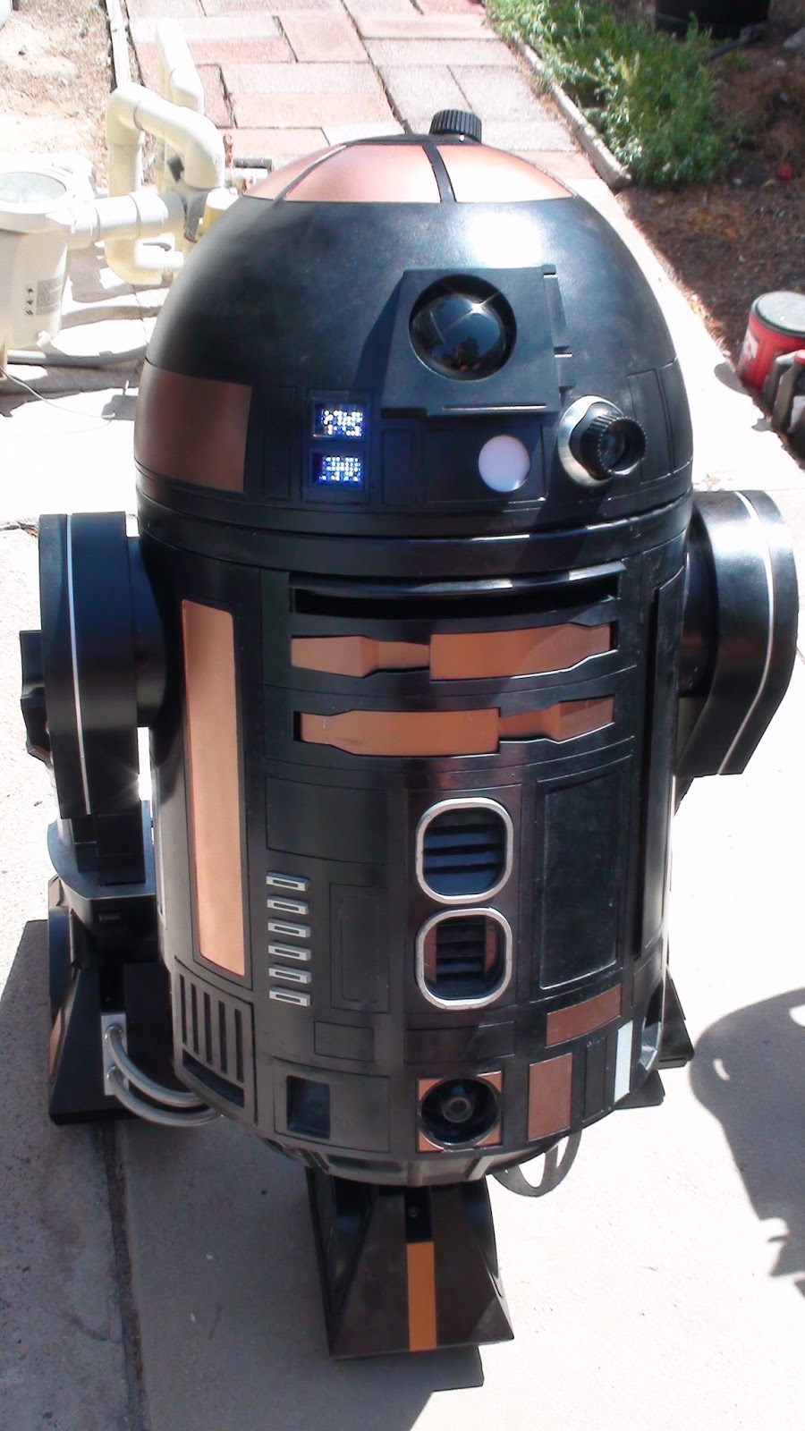

1 other thing that is not screen accurate are the silver hydro piston thingys are supposed to be black instead of silver. I just think it looks cooler with silver than black, because otherwise hell the entire droid is just black.


I can't stop now. I've learned so much over the past 5 years I want to apply all the cool things I did with my R5 and do all of that in this droid where I can.
So I plan to install servos to control atleast the front holoprojector and install some LED light in the front and back and a red light on the top HP.
I'm going to open all the front skin doors and I'm going to use my droid Zapper to come out the little front door on the left like you see when R2-D2 zaps the chain off Leia to free her. I'm going to replicate that since this is a ROTJ droid.
I'm also going to get the utility arms to open and close with servos like I'm currently working on for R5. I have plenty of servos and time to take this to the max.
Let's hope they have plenty of imperial droids in Rogue One!
Monday, April 25, 2016
Getting R2-Q5 on 3 feet and realizing I have a big problem.
Getting the droid on 3 feet is a massive accomplishment, until you see some thing has gone terribly wrong.
 I know I got the center foot properly, that pretty much can't be screwed up. But these feet are way off or atleast one of them is. So I looked over at my other R2-D2 to find out what is the proper distance to give me some idea.

The leg on the left is correct the leg on the right of this photo is sticking out way to far. No way I'll hook up the drive system and try to drive this and break something.
 Here is a few from the side. How is this even possible? Both the legs simply bolt onto the frame and I had this droid in 2 legged position before and on my first time on 3 legs its all messed up. At this point I don't know whether to laugh, cry, get mad or head to the creature cantina and shine one on. All I can think of now is Captin Picard.
 How many thousands done the drain for a crooked droid? What short bus did this guy come off from? Surely this can't be the fault of the man who designed these, they'd never sell so many and I'd be the first who caught this? No way the error has to be on my end. So I study the droid and figure the right leg is the one that is not done right, but how?
 After taking some measurements on the side plates I found out the screw holes didn't match the the left plate. I highlighted the 2 top holes with red circles.
The left hole in the rear comes down 2.1 inches and the other hole is about 1. 3/4 of an inch down. That's enough to make the difference so the fix here is just to take the parts off that mount the skins mount to then flip the plate around 180 degree and put the leg back on as my awesome green arrows I drew clearly show.
 That fixed him:)
So then the moment of truth, I wire up the legs turn him on and get ready to see him move for the first time in 5 years. The sound track of Rocky starts in the background I power on my transmitter and get ready to scream out "I did it Adrian I did it!" Then I turn on my droid and wait for him to breath and come alive.
Nothing, lights are on the electronics on but all radio control has died in the past 2 hours somehow. That turned out be a loose connection but he runs now. That happened when I installed a strap to hold both batteries to the frame so I can tilt him without the batteries falling through the robot.I think I should replace that electronic parts as it can/will stop me from RC in the future now that I know that needs more solder somewhere.
 I'll be tweaking that next to my liking but "I did it Adrian I did it!"


The leg on the left is correct the leg on the right of this photo is sticking out way to far. No way I'll hook up the drive system and try to drive this and break something.



The left hole in the rear comes down 2.1 inches and the other hole is about 1. 3/4 of an inch down. That's enough to make the difference so the fix here is just to take the parts off that mount the skins mount to then flip the plate around 180 degree and put the leg back on as my awesome green arrows I drew clearly show.

So then the moment of truth, I wire up the legs turn him on and get ready to see him move for the first time in 5 years. The sound track of Rocky starts in the background I power on my transmitter and get ready to scream out "I did it Adrian I did it!" Then I turn on my droid and wait for him to breath and come alive.
Nothing, lights are on the electronics on but all radio control has died in the past 2 hours somehow. That turned out be a loose connection but he runs now. That happened when I installed a strap to hold both batteries to the frame so I can tilt him without the batteries falling through the robot.I think I should replace that electronic parts as it can/will stop me from RC in the future now that I know that needs more solder somewhere.

Feet Assembly
I had the center food done a while ago and now its time to install it. I didn't want to remove the batteries and start unwiring that so I lay the droid on its side and slip up the batteries just enough to reach the screws. I swapped out the Philips heads for Allen wrench head.


Here is a bit of a close up. I found this much easier to use a 90 degree tool to bolt that in then a screw driver.
I have 1 leg ready so I turned the droid a bit and bolted that leg on. Next up is putting together one of the outer foots. There is a certain order for this to be done that makes it easier so read along.
 1. First you install the hoses into the battery box.
2. Then you install the hoses in the foot and don't forget the foot strip, its easier to do this now and about impossible after the foot drive is installed.
 3. Now you can install the ankle to the foot, you can also do this after the foot drive is but its easier to do it now.
 4. Install the foot details on the side. If you install the foot drive system you can't install these parts as there is no room to reach the bolts. I learned all of this the hard way with trial and error until I found a good way to put this together. Despite the fact I painted these feet and related parts over and over again to get them perfect. Just be ready to see additional scratches as this don't exactly slide together easily. I think later I can just buy an airbrush and do touch up on parts I don't like.
 Such as the other foot I did last week. When I put this together the foot strip did a 180 swing and scratched in a smily face into my fresh paint. Damn it! I refuse to take this apart and try to get it assembled perfect. Some masking tape and an airbrush will fix this up later.
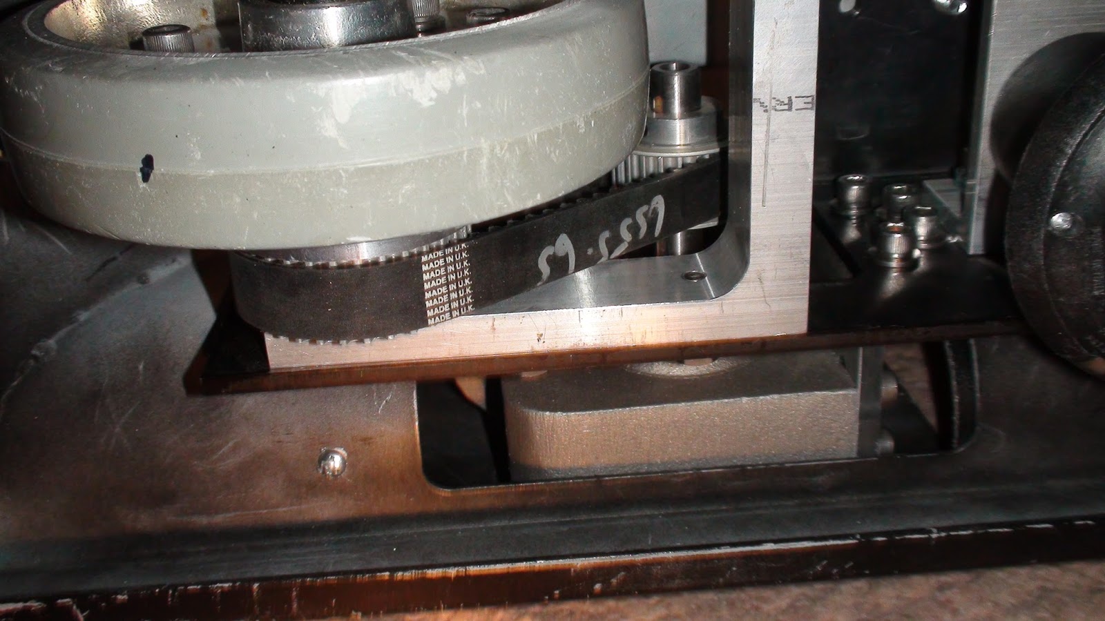
 5. Anyway now you install the foot drive system in my case it's an original JAG foot drive with 1 wheel.
 6. Install the NPC motor now and then you shove the wheel and get the belt as tight as you can and tighten the 4 bolts. DO NOT have the wheel in the position you want and then install the NPC that will make the NPC motor a bit crooked. Now slide the battery box over the NPC motor.
 7. I used 2 self tapping sheet metal screws to attach the batter box to the foot shell. I got a nice and solid fit doing this. I'm using battery boxes supplied by R2 member Matt and they are really nicely done.
 8. This is where I placed the other screw to keep it bolted on. I hope the foot is somewhat level if the rear omni ball is too high I'll have to take it apart and adjust it. As a rule of thumb the droid only drives on the wheels and not the wheels and the omni ball. Most have the omni ball about a 1/4 inch lower than the wheel and the omni ball is sort of a backup system form when your droid takes a hard stop or goes in reverse.
Other misc problems doing your install.
 There is a good chance you're going to have to grind down the top of the NPC motors or the battery boxes probably won't fit. This is kind of a right of passage for a builder.

Not everything is easy peasy what I find is my foot drive is about 1/8 of an inch off the center channel as the red arrow in the image above shows. The green dots I paint in the U channel are where I should have drilled the holes. So 1 side of the NPC needed more grinding than the other side needed. Make sure the foot drive is centered perfectly in the U channel of your foot shells or there will be hell to pay!
 What kind of hell to pay? This kind of hell! As I said before if you don't have this centered too well as I found out. You might be grinding extremely deeply into 1 side of your NPC motor is the hell you'll pay of screwing up $320.00 in motors and close to $900.00 for your foot shells you wrecked and need to have spot welded to save it. Read, read read alot of blogs before you try to wing this like I do!
 This part I got from 'somewhere' I don't remember that are dual nuts to hold the hose in the battery box didn't line up. So I just cut that in half with a dremel, no biggie.
Last tip: Don't put any clear coat of paint on any of your parts as they might get messed up in assembly and you never known when final assembly is until its sat for months completed. I plan to air brush the parts later to fix them. This black Death Star Droid should have NO weathering, not until the Death Star blows up, until then it was shiny and clean looking.
Also don't use loctite (yet) because as a droid builder you never know how many times you have to take these various areas apart until you have parts just where and the color you want them. I'll probably be taking these feet apart several more times to adjust the feet level if needed and other things that will pop up. I know how R2 builders think, install something use loctite and think " This part is done, I can cross that off the bucket list". No part is ever done, you're just done with it for now...

Here is a bit of a close up. I found this much easier to use a 90 degree tool to bolt that in then a screw driver.
I have 1 leg ready so I turned the droid a bit and bolted that leg on. Next up is putting together one of the outer foots. There is a certain order for this to be done that makes it easier so read along.

2. Then you install the hoses in the foot and don't forget the foot strip, its easier to do this now and about impossible after the foot drive is installed.


Other misc problems doing your install.


Not everything is easy peasy what I find is my foot drive is about 1/8 of an inch off the center channel as the red arrow in the image above shows. The green dots I paint in the U channel are where I should have drilled the holes. So 1 side of the NPC needed more grinding than the other side needed. Make sure the foot drive is centered perfectly in the U channel of your foot shells or there will be hell to pay!


Last tip: Don't put any clear coat of paint on any of your parts as they might get messed up in assembly and you never known when final assembly is until its sat for months completed. I plan to air brush the parts later to fix them. This black Death Star Droid should have NO weathering, not until the Death Star blows up, until then it was shiny and clean looking.
Also don't use loctite (yet) because as a droid builder you never know how many times you have to take these various areas apart until you have parts just where and the color you want them. I'll probably be taking these feet apart several more times to adjust the feet level if needed and other things that will pop up. I know how R2 builders think, install something use loctite and think " This part is done, I can cross that off the bucket list". No part is ever done, you're just done with it for now...
Wednesday, April 6, 2016
R2-Q5 Electronics
I've been working on this droid alot lately but haven't blogged my progress in a while.
My old batteries which barely got used were old and died. So I have new batteries and I've made my own electronics board out of 12x12 inch by 1/4 inch thick aluminum.


 I took some photos of the switch settings on the motor controls for future reference.
My old batteries which barely got used were old and died. So I have new batteries and I've made my own electronics board out of 12x12 inch by 1/4 inch thick aluminum.

The panel has holes that I have 1/4 inch hand studs that attach to some L brackets mounted on the frame. I can in about 1 minute unscrew the 3 bolts and unplug main power then disconnect and take all of it out if I need to.


Subscribe to:
Posts (Atom)